Hướng dẫn lắp đầu báo khói địa chỉ FSP-951, FSP-851
Hướng dẫn lắp đặt đầu báo khói địa chỉ FSP-951, FSP-851
SPECIFICATIONS
Base Diameter: 4.0 inches (10.2cm)
Base Height: .74 inches (18.8 mm)
Operating Temperature: Refer to applicable sensor Operating Temperature Range using the Base/Sensor Cross Reference Chart at systemsensor.com
Electrical Ratings – includes base and detector
Operating Voltage: 15 to 32 VDC
Standby Current: 150µA
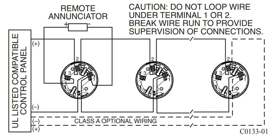
Các chân của để B501 với các đầu nối vít được cung cấp cho nguồn (+) và (-) , kết nối và giao tiếp diễn ra qua đường dây nguồn (+) và (-)
Cách đấu nối cho đế đầu báo và kết nối với nhiều đầu báo.
Tham khảo sản phẩm
BEFORE INSTALLING
Please read the System Smoke Detectors Application Guide, which provides
detailed information on detector spacing, placement, zoning, wiring, and special applications. Copies of this application guide are available from System
Sensor. NFPA 72 guidelines should be observed.
NOTICE: This manual should be left with the owner/user of this equipment.
IMPORTANT: The detector used with this base must be tested and maintained
regularly following NFPA 72 requirements. The detector should be cleaned at
least once a year.
For signal wiring (the wiring between interconnected detectors and modules),
it is recommended that the wiring be no smaller than 18 AWG (0.823 square
mm). Wire sizes up to 12 AWG (3.31 square mm) may be used with the base.
Alarm system control panels have specifications for allowable loop resistance.
Consult the control panel specifications for the total loop resistance allowed
before wiring the detector loops.
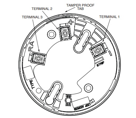
Make wiring connections by stripping about 3⁄8 inch (10 mm) of insulation
from the wire end (use strip gauge molded in base). Then slide the wire under
the clamping plate and tighten the clamping plate screw. Do not loop the wire
under the clamping plate. (see Figure 3)
Check the zone wiring of all bases in the system before installing the detectors. This includes checking the wiring for continuity, correct polarity, ground
fault testing and performing a dielectric test.
The base includes an area for recording the zone, address, and type of detector to be installed at that location. This information is useful for setting the
detector head address and for verification of the detector type required for
that location.
Once all detector bases have been wired and mounted, and the loop wiring
has been checked, the detector heads may be installed in the bases.
